hewball.com.au A little bit Photography and a lot Suzuki Mightyboy

February 5, 2016

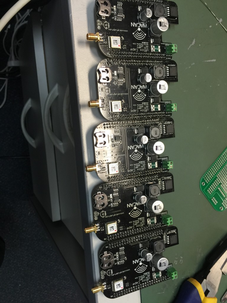
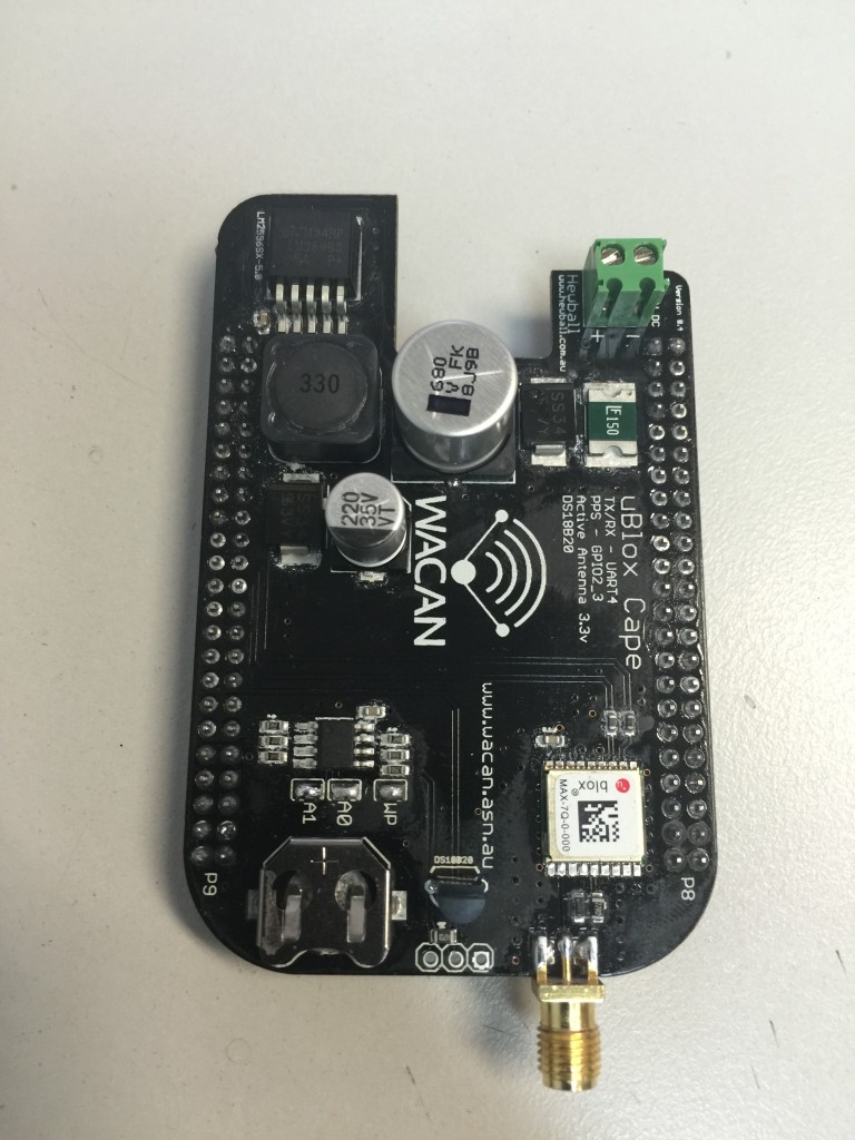
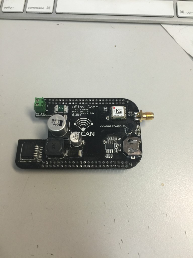
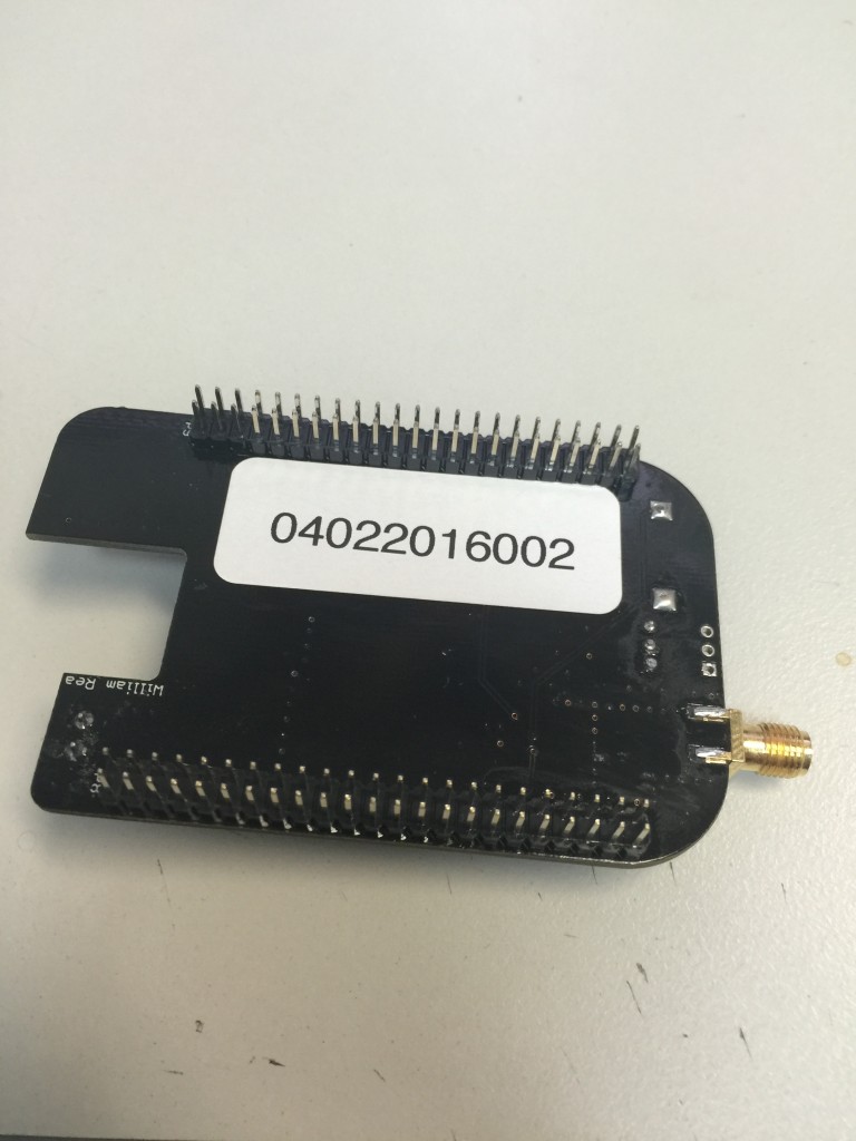
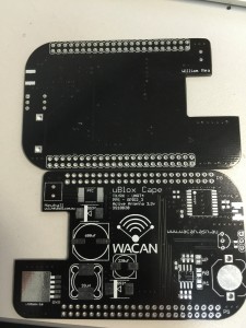
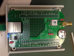
Version 4 Beaglebone U-blox GPS Cape

Filed under: Technology — Tags: , , , , , , , — hewball @ 10:10 pm

finally got back to building some cape from stock i had on hand with the new boards i ordered many moons ago

just a power input pin fix and some pretty labelling

also in these pictures are the Dallas 1wire temp sensors soldered on, with pins broken out for add on sensors

EEPROM Solder Jumpers WP Bridged enables eeprom write
A0 and A1 Bridge equal Cape Manager Cape Slot Zero  and i2c reference number of 2-0054

in Kernel 4 nvmem changes have become mainline too
so eeprom is now at
for Cape Slot Zero   “/sys/bus/nvmem/devices/at24-1/nvmem”  not the old location of “/sys/bus/i2c/devices/1-0054/eeprom”
i2c bus reference for eeproms also changed from 1 to 2 for reasons…


2016-02-04 11.12.112016-02-04 12.27.26 2016-02-05 16.27.37 2016-02-05 16.27.30 2016-02-05 16.27.25


Overlays for Kernel Version 4 and above

Shane worked up the DTS file for all the features on this cape


These are wrong new ones soon
BBB-WACAN-GPS-00A0.dts
BBB-WACAN-GPS-00A0  dts and dtbo

November 19, 2014

Version 3 Beaglebone Ublox GPS Cape

Filed under: Technology — Tags: , , , — hewball @ 12:28 pm


Version 3, Just arrived for testing now, this one includes a power supply on cape capable of upto 33v DC input, and with the nice logo added

2014-11-19 12.18.00

August 5, 2014

Beaglebone Black GPS

Filed under: Technology — Tags: , , , , , , , — hewball @ 8:46 pm

given that a straight GPS cape for Beaglebone didnt exist, the only thing to do is to make one with the help of “Wrea”, thanks for that 😀

Based off the Protocape with eeprom from logicsupply.com

making use of the Ublox Max-7Q GPS

Uses Uart4 for serial lines which breakout to pins P9.11 and P9.13

and For Pulse Per Second output from the GPS for NTP it uses pin P8.8 also known as gpio2_3

has jumper for Active GPS antenna power and also a connector for Dallas 1 Wire devices

Beaglebone Black GPS Cape

Device Tree Overlay

BBB-WACAN-GPS-00A0

June 18, 2014

Beaglebone Black Pin Mux

Filed under: Technology — Tags: — hewball @ 11:34 am

Found this Saving for later!!! http://hipstercircuits.com/enable-serialuarttty-on-beaglebone-black/

Finding the numbers for muxing pins
I have yet to find a good explanation for the pin mux hex numbers. I discovered I had actually written it up myself in a previous post, but I’ll repeat it here for convenience.

In the above example you have the following:

0x070 0x26  /* P9_11 = GPIO0_30 = GPMC_WAIT0 , MODE6 */

The first number is the offset from the first pin (conf_gpmc_ad0). The second number is the mode and direction etc. Cameon has an explenation of the second number. Reprinted here for convenience:

  • Bit 5: 1 – Input, 0 – Output
  • Bit 4: 1 – Pull up, 0 – Pull down
  • Bit 3: 1 – Pull disabled, 0 – Pull enabled
  • Bit 2 \
  • Bit 1   |- Mode
  • Bit 0 /

The following is a list of the first numbers for all the pins that have been broken out on the Beaglebone.

So if you want to mux pin 6 from the P8 header to mode 7 (GPIO) and output, you say:

0x0C 0×07 /* P8_6 = GPIO1_3 -> Mode7, output. */

Here is a table of all the pins that are broken out with their corresponding numbers and names:

P8_1 GND P9_1 GND
P8_2 GND P9_2 GND
P8_3 0×18 GPIO1_6 gpmc_ad6 P9_3 DC_3.3V
P8_4 0x1C GPIO1_7 gpmc_ad7 P9_4 DC_3.3V
P8_5 0×08 GPIO1_2 gpmc_ad2 P9_5 VDD_5V
P8_6 0x0C GPIO1_3 gpmc_ad3 P9_6 VDD_5V
P8_7 0×90 TIMER4 gpmc_advn_ale P9_7 SYS_5V
P8_8 0×94 TIMER7 gpmc_oen_ren P9_8 SYS_5V
P8_9 0x9C TIMER5 gpmc_be0n_cle P9_9 PWR_BUT
P8_10 0×98 TIMER6 gpmc_wen P9_10 SYS_RESETn RESET_OUT
P8_11 0×34 GPIO1_13 gpmc_ad13 P9_11 0×70 UART4_RXD gpmc_wait0
P8_12 0×30 GPIO1_12 GPMC_AD12 P9_12 0×78 GPIO1_28 gpmc_be1n
P8_13 0×24 EHRPWM2B gpmc_ad9 P9_13 0×74 UART4_TXD gpmc_wpn
P8_14 0×28 GPIO0_26 gpmc_ad10 P9_14 0×48 EHRPWM1A gpmc_a2
P8_15 0x3C GPIO1_15 gpmc_ad15 P9_15 0×40 GPIO1_16 gpmc_a0
P8_16 0×38 GPIO1_14 gpmc_ad14 P9_16 0x4C EHRPWM1B gpmc_a3
P8_17 0x2C GPIO0_27 gpmc_ad11 P9_17 0x15C I2C1_SCL spi0_cs0
P8_18 0x8C GPIO2_1 gpmc_clk_mux0 P9_18 0×158 I2C1_SDA spi0_d1
P8_19 0×20 EHRPWM2A gpmc_ad8 P9_19 0x17C I2C2_SCL uart1_rtsn
P8_20 0×84 GPIO1_31 gpmc_csn2 P9_20 0×178 I2C2_SDA uart1_ctsn
P8_21 0×80 GPIO1_30 gpmc_csn1 P9_21 0×154 UART2_TXD spi0_d0
P8_22 0×14 GPIO1_5 gpmc_ad5 P9_22 0×150 UART2_RXD spi0_sclk
P8_23 0×10 GPIO1_4 gpmc_ad4 P9_23 0×44 GPIO1_17 gpmc_a1
P8_24 0×04 GPIO1_1 gpmc_ad1 P9_24 0×184 UART1_TXD uart1_txd
P8_25 0×00 GPIO1_0 gpmc_ad0 P9_25 0x1AC GPIO3_21 mcasp0_ahclkx
P8_26 0x7C GPIO1_29 gpmc_csn0 P9_26 0×180 UART1_RXD uart1_rxd
P8_27 0xE0 GPIO2_22 lcd_vsync P9_27 0x1A4 GPIO3_19 mcasp0_fsr
P8_28 0xE8 GPIO2_24 lcd_pclk P9_28 0x19C SPI1_CS0 mcasp0_ahclkr
P8_29 0xE4 GPIO2_23 lcd_hsync P9_29 0×194 SPI1_D0 mcasp0_fsx
P8_30 0xEC GPIO2_25 lcd_ac_bias_en P9_30 0×198 SPI1_D1 mcasp0_axr0
P8_31 0xD8 UART5_CTSN lcd_data14 P9_31 0×190 SPI1_SCLK mcasp0_aclkx
P8_32 0xDC UART5_RTSN lcd_data15 P9_32 VADC
P8_33 0xD4 UART4_RTSN lcd_data13 P9_33 AIN4
P8_34 0xCC UART3_RTSN lcd_data11 P9_34 AGND
P8_35 0xD0 UART4_CTSN lcd_data12 P9_35 AIN6
P8_36 0xC8 UART3_CTSN lcd_data10 P9_36 AIN5
P8_37 0xC0 UART5_TXD lcd_data8 P9_37 AIN2
P8_38 0xC4 UART5_RXD lcd_data9 P9_38 AIN3
P8_39 0xB8 GPIO2_12 lcd_data6 P9_39 AIN0
P8_40 0xBC GPIO2_13 lcd_data7 P9_40 AIN1
P8_41 0xB0 GPIO2_10 lcd_data4 P9_41 0x1B0 CLKOUT2 xdma_event_intr1
P8_42 0xB4 GPIO2_11 lcd_data5 P9_42 0×164 GPIO0_7 eCAP0_in_PWM0_out
P8_43 0xA8 GPIO2_8 lcd_data2 P9_43 GND
P8_44 0xAC GPIO2_9 lcd_data3 P9_44 GND
P8_45 0xA0 GPIO2_6 lcd_data0 P9_45 GND
P8_46 0xA4 GPIO2_7 lcd_data1 P9_46 GND

November 10, 2011

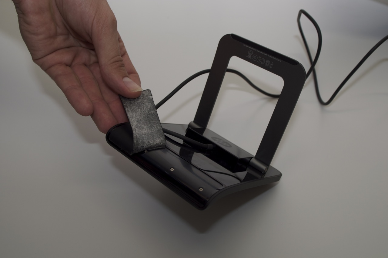
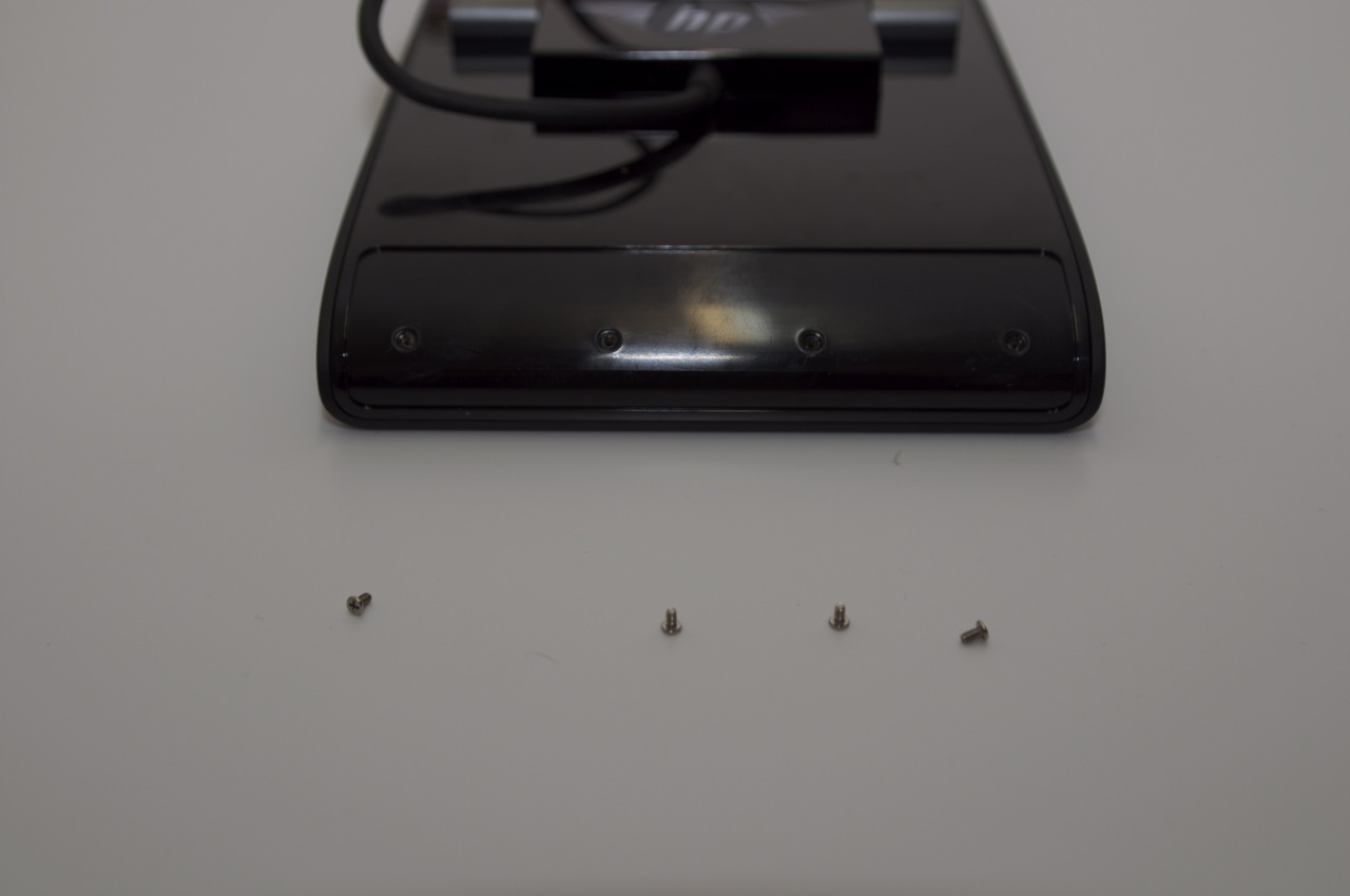
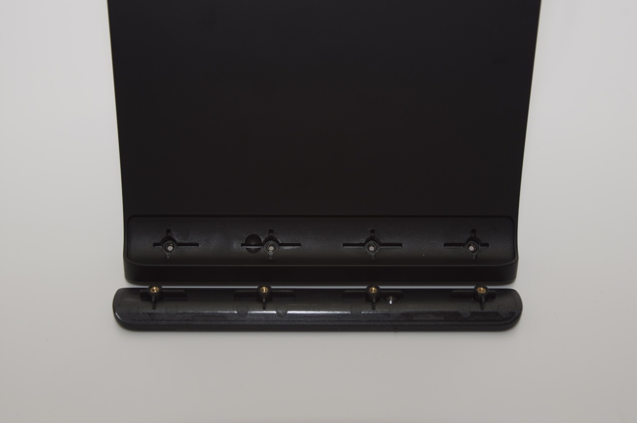
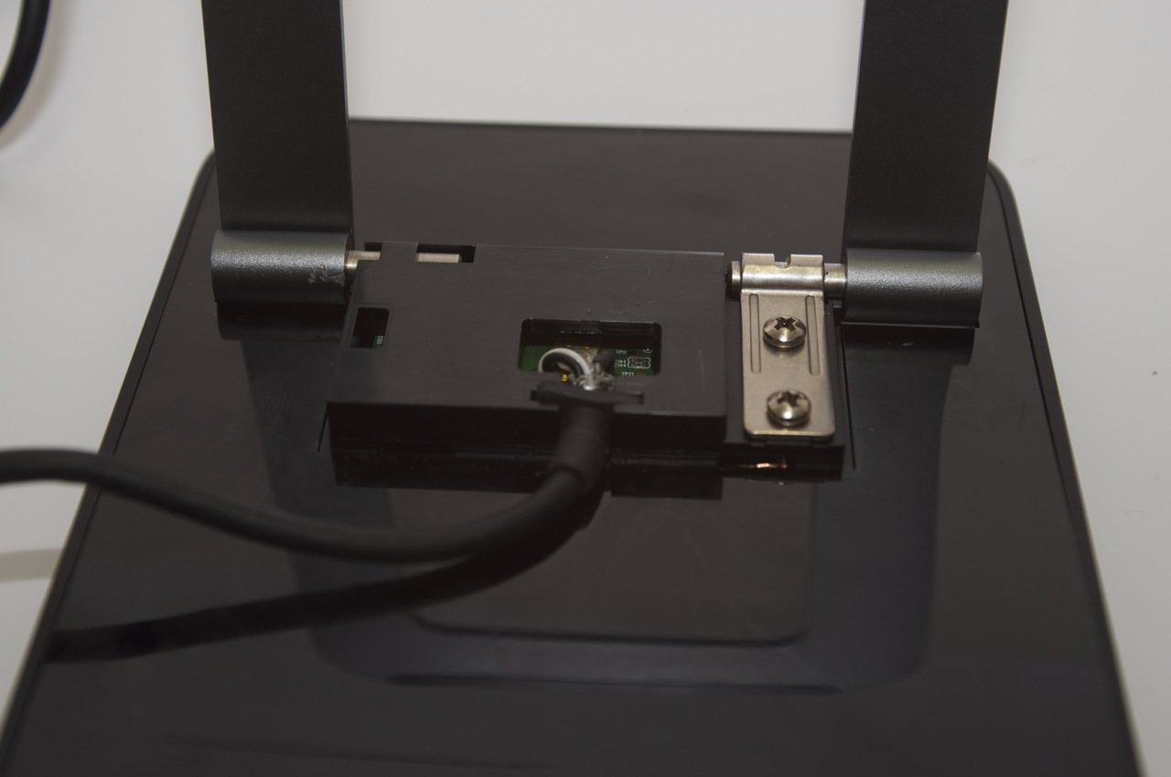
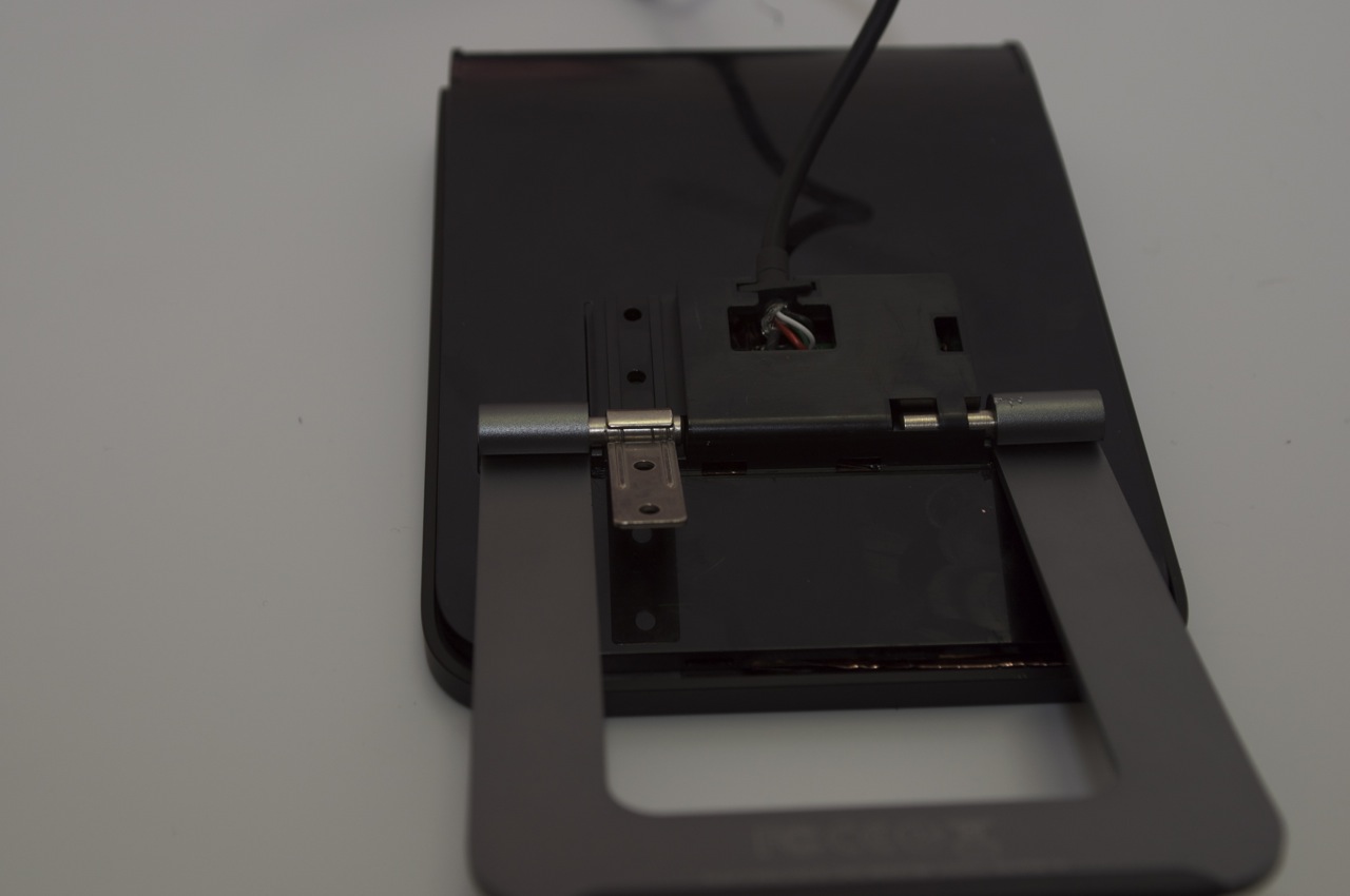
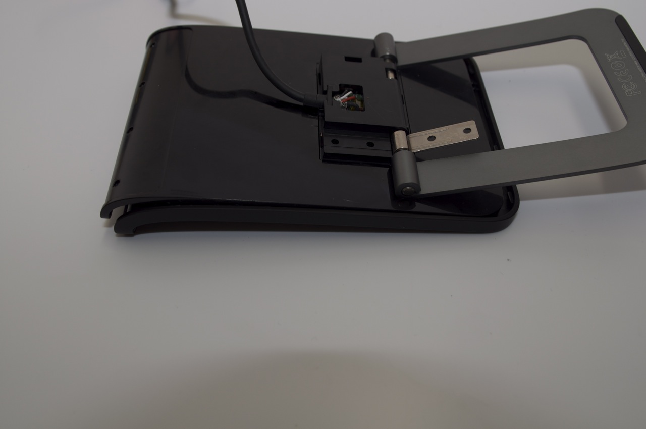
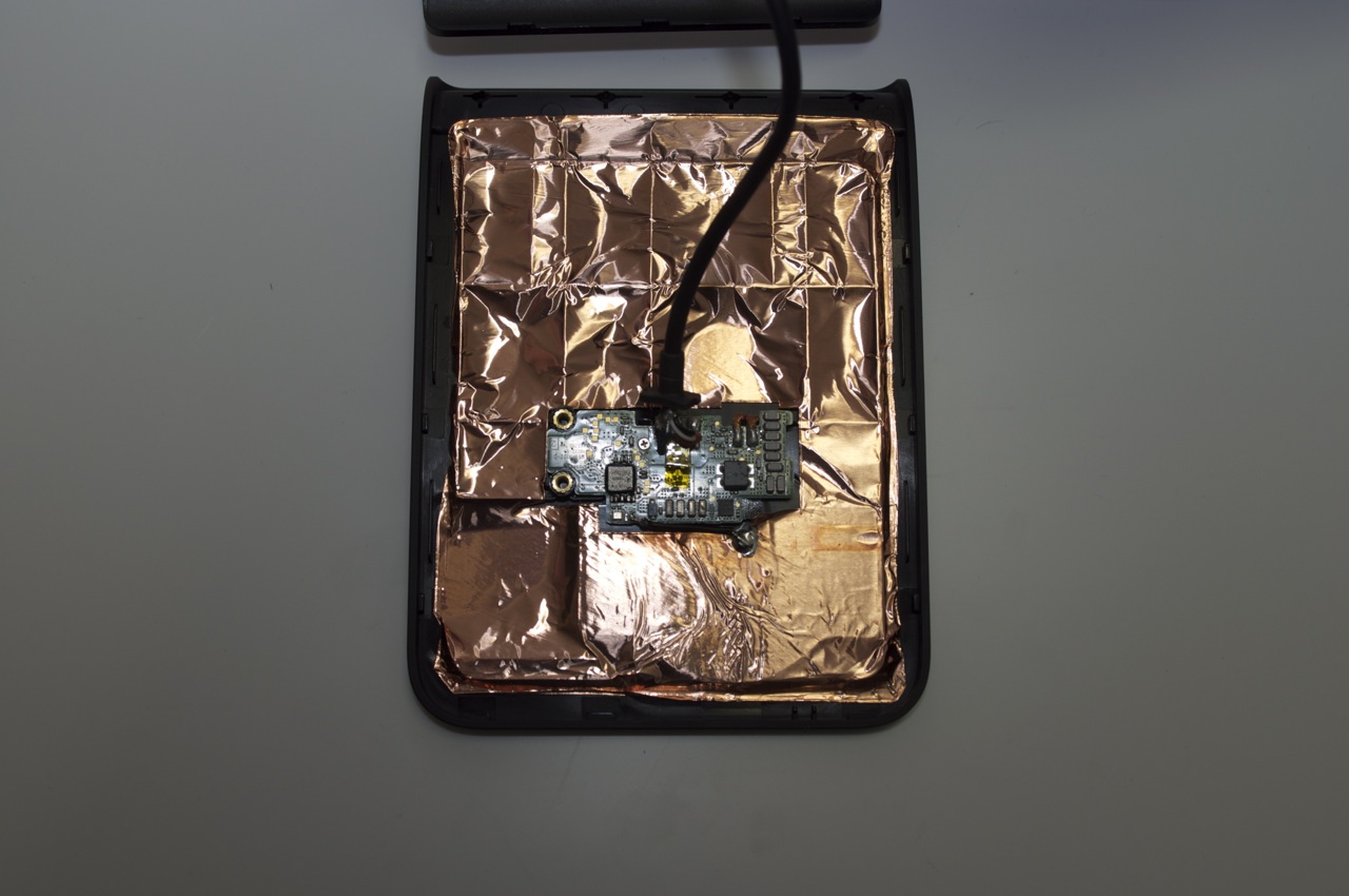
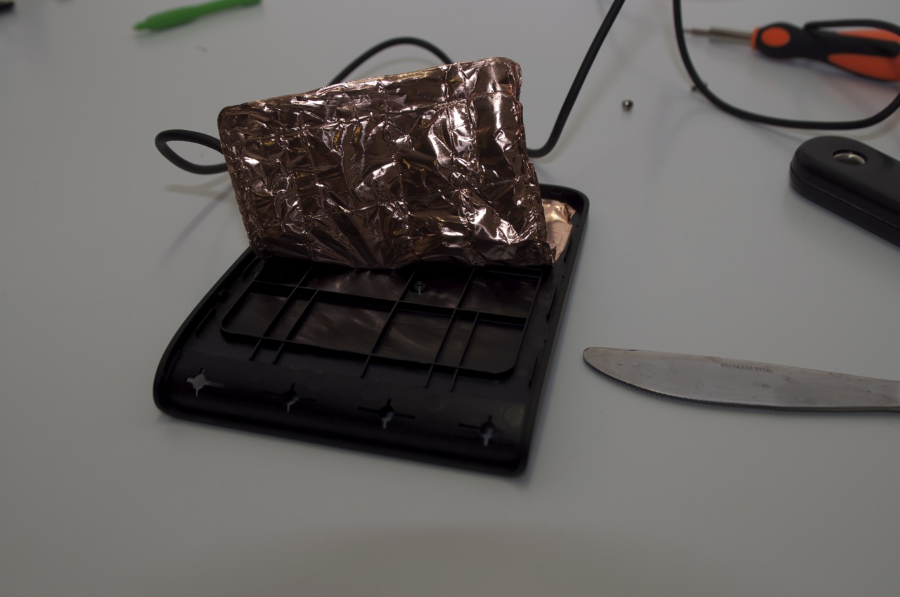
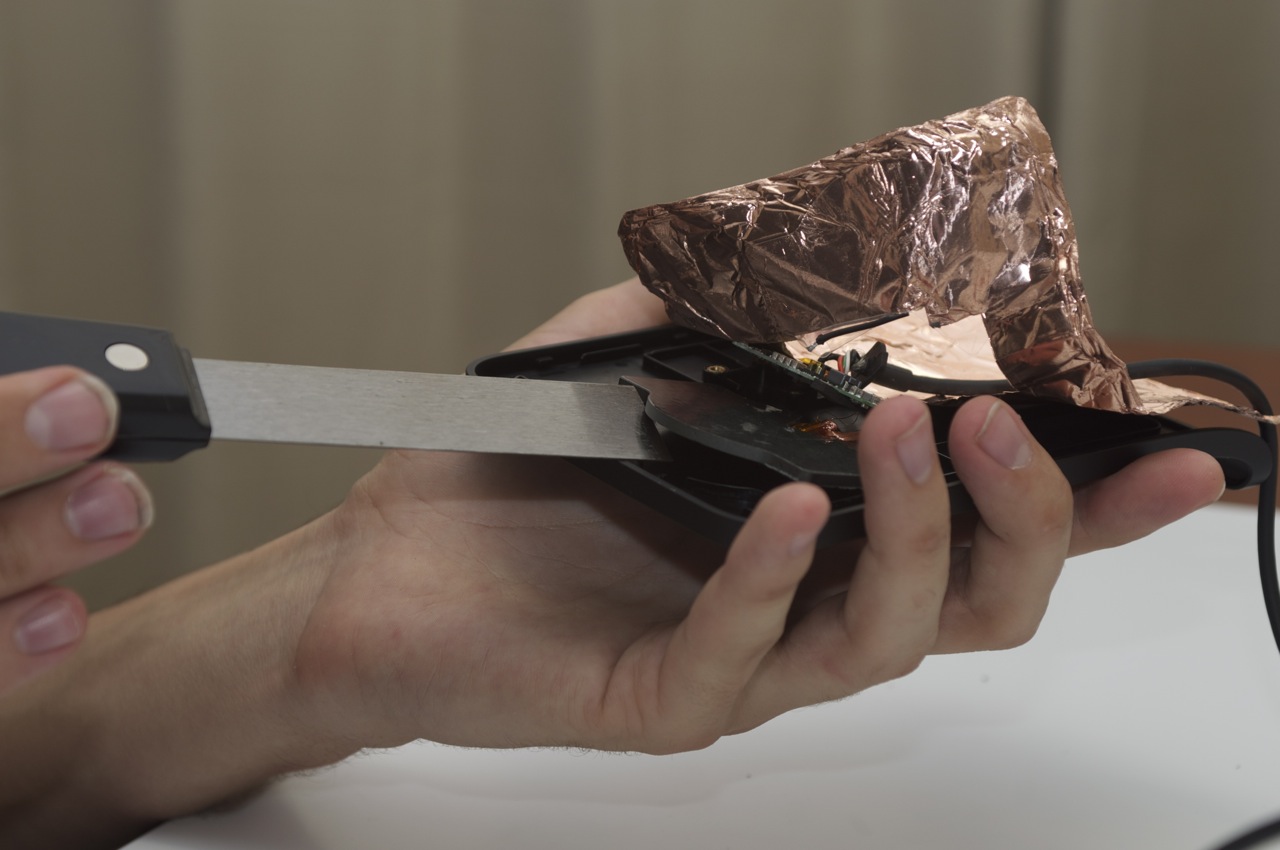
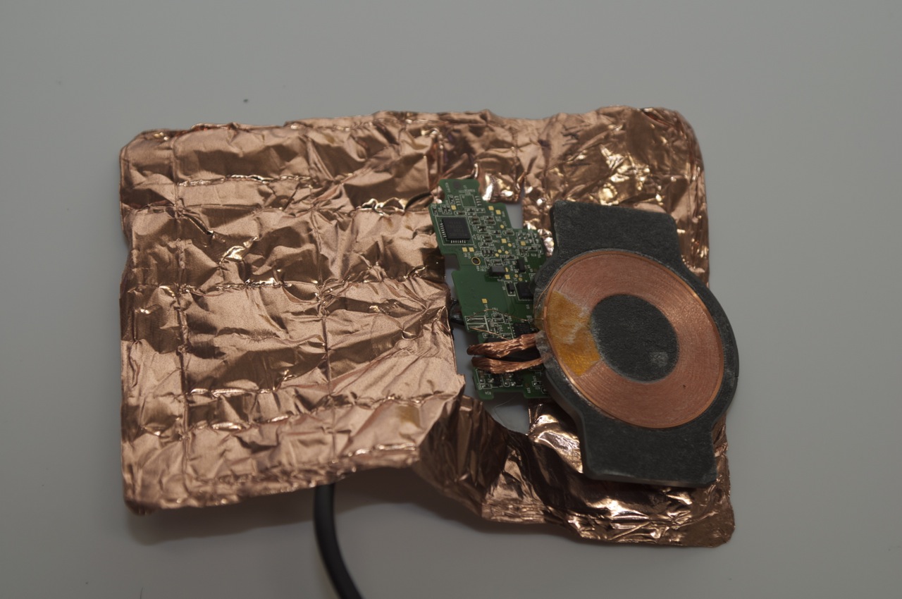
Touchpad Touchstone Dismantled

Filed under: Technology,Touchpad,WebOS — Tags: , , , , , — hewball @ 11:33 pm

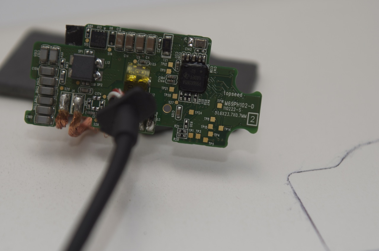
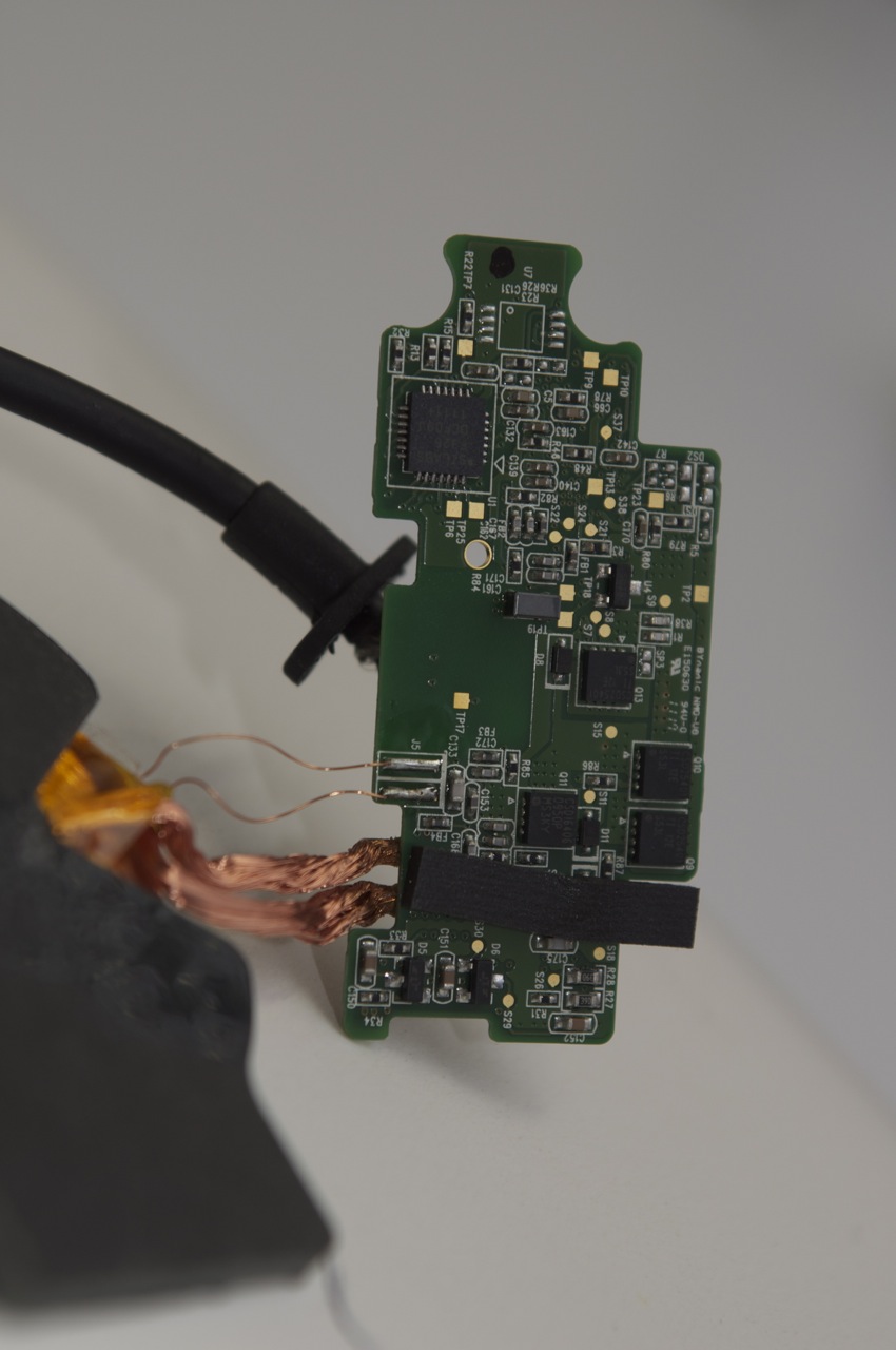
Visuals of Inside a HP Touchpad Touchstone


November 4, 2011

HP Touchpad USB Audio

Filed under: Technology,Touchpad,WebOS — Tags: , , , , , , , , , — hewball @ 10:34 am

So it seems the touchpad is quite a powerful little device under to hood, a few kernel changes, config changes to pulseaudio and USB audio support is added, better sound out of the touchpad than the headphone port.

To get this working it required an OTG micro USB cable, powered USB hub that feeds power back to the source usb plug, and some form of usb HID sound device,  pretty much any usb sound card that uses the line “No Drivers Required” with the support of MacOS is a dead giveaway this is what it is, i came across this http://www.TurtleBeach.com/products/sound-cards/audio-advantage-micro-ii.aspx  USB with optical output on the cheap, waiting for it to arrive to see how well this device works.

With the help of @therealsconix and his PulseAudio Settings App in Preware switching to usb audio after a bit of testing became simple

last thing that is left is getting the USB audio support included in the Kernels in Preware, until this time if you want my uberkernel with this working let me know

November 2, 2010

Open Mesh Firmware Flashing Pico2HP

Filed under: Technology — Tags: , , , , , , — hewball @ 10:14 pm

Flashing a Picostation2 HP with open mesh firmware.

Problem: The Boot timeout (in the redboot boot loader) is too short to successfully flash the devices with a non Ubiquiti Firmware. So before you can flash a new firmware we need to increase the timeout.

Ingredients: You are going to need the following files in a folder of your choosing

· putty.exe – download from http://www.chiark.greenend.org.uk/~sgtatham/putty/download.html

· open-mesh-flash.exe – downloaded from http://open-mesh.com/

· breakin.bat and redboot.txt – grab the text below, Note – copy everything BETWEEN the denoting lines, but NOT the denoting lines themselves

— breakin.bat —
echo off
:start
rem ————————————————
ping 192.168.1.20 -n 1 -w 1 > NULL
echo .
IF ERRORLEVEL 1 goto start
rem ————————————————
break
putty.exe telnet://192.168.1.20:9000 -m redboot.txt
— end —

— redboot.txt —
^C
— end —

Method: The idea behind the script is that it will ping the PicoStation2 until it responds and then it launches a telnet session with putty and sends the Control+C command to stop the boot process and give you a terminal.

With that in mind, fire up a command prompt on your windows machine and start running the breakin.bat script.

Once the script is running, plug your PicoStation2 into the network. It should only take a few seconds for the script to break into the boot process. If after 20 seconds you do not have a putty telnet session window open, unplug the device, wait for 20 seconds and try again.

Now that you have a putty telnet session open, you should see similar to the following:

== Executing boot script in 0.090 seconds – enter ^C to abort
^C
RedBoot>
Now that you have a command prompt, you need to run the fconfig command and change the settings. Note: To delete a character, use Control+H (^H) – It does not delete the character on screen, but it does delete the character! Note: Use the enter key to get to the next line (setting)

Here is a screen dump of me changing the config on one of the devices

== Executing boot script in 0.090 seconds – enter ^C to abort
^C
RedBoot> fconfig
Run script at boot: true
Boot script:
.. fis load -l vmlinux.bin.l7
.. exec
Enter script, terminate with empty line
>>
Boot script timeout (1000ms resolution): 1^H2
Use BOOTP for network configuration: false
Gateway IP address:
Local IP address: 192.168.1.20
Local IP address mask: 255.255.255.0
Default server IP address:
Console baud rate: 9600
GDB connection port: 9000
Force console for special debug messages: false
Network debug at boot time: false
Update RedBoot non-volatile configuration – continue (y/n)? y
… Erase from 0xa87e0000-0xa87f0000: .
… Program from 0x80ff0000-0x81000000 at 0xa87e0000: .
RedBoot> reset

So now you have a PicoStation2 with a two second boot timeout it is time to flash it. Use the following steps to get your device flashed. 1. Determine the interface your device it attached to (run the open-mesh-flash.exe without parameters to see a list)

2. Run the open-mesh-flash.exe specifying your interface

3. Plug your PicoStation2 in

4. Watch the magic happen!

Full instructions can be found at this URL http://support.open-mesh.com/activekb/questions.php?questionid=24

Other Gotcha’s

Stuck In Redboot

Run Breakin.bat

Corect

== Executing boot script in 0.090 seconds – enter ^C to abort
^C
RedBoot> fconfig
Run script at boot: true
Boot script:
.. fis load -l vmlinux.bin.l7
.. exec

Broken

== Executing boot script in 0.090 seconds – enter ^C to abort
^C
RedBoot> fconfig
Run script at boot: true
Boot script:
..

Clearing Device For fresh Reflash

RedBoot> fis list
Name FLASH addr Mem addr Length Entry point
RedBoot 0xA8000000 0xA8000000 0x00030000 0x00000000
linux 0xA8030000 0x80041000 0x00660000 0x80041000
FIS directory 0xA87E0000 0xA87E0000 0x0000F000 0x00000000
RedBoot config 0xA87EF000 0xA87EF000 0x00001000 0x00000000
RedBoot> fis init
About to initialize [format] FLASH image system – continue (y/n)? y
*** Initialize FLASH Image System
… Erase from 0xa87e0000-0xa87f0000: .
… Program from 0x80ff0000-0x81000000 at 0xa87e0000: .
RedBoot> fis list
Name FLASH addr Mem addr Length Entry point
RedBoot 0xA8000000 0xA8000000 0x00030000 0x00000000
FIS directory 0xA87E0000 0xA87E0000 0x0000F000 0x00000000
RedBoot config 0xA87EF000 0xA87EF000 0x00001000 0x00000000
RedBoot>

Attempt a reflash with openmesh
Powered by WordPress